[MrGibson.com Home]
Odyssey2 Computer Intro!
Assembler and Machine Hex Manual

What you need to know before you program in Computer Intro!
- Program code and data space is limited to 99 steps.
- Data space strings are (or should be) terminated with a NULL (HEX 00)
- Mathematical operations are in BSD.
- The computer has 16 registers and an accumulator that can hold 8 bits (1 byte) of data each.
- Chracter set is limited to 64 character, (the official book describes only 63).
- There are additional functions in this manual not addressed in the official book.


Appendix A: Single button editor functions P to Program Mode A to enter Assembler code I to Insert code M to enter Machine hex code I to Insert code R for Roll code D to roll Down U to roll Up [RESET] TO STORE PROGRAM E to Execute code Mode D Display Mode (registers, counters, accumulators) 0-F for registers P for Program counter S for Subroutine counter X for accumalator C Continue Mode
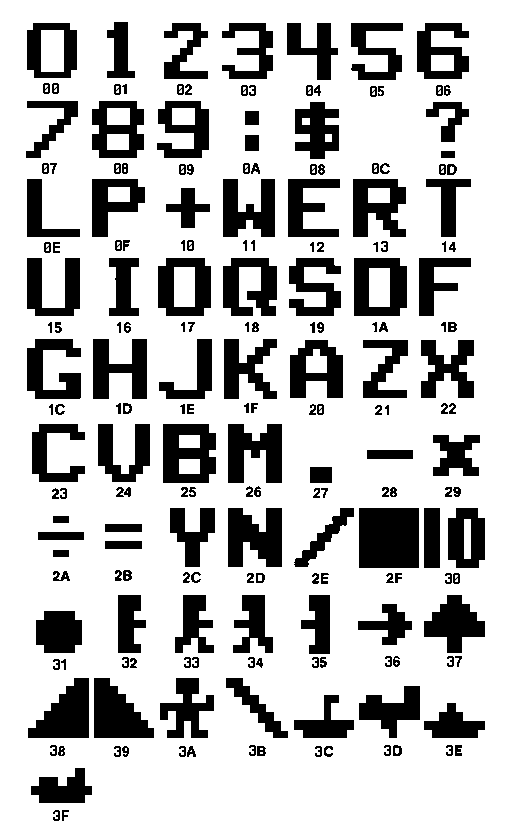
Appendix B: Odyssey2 Character Set
#   HEX  Character     #   HEX  Character
0   00   0             32  20   A             
1   01   1             33  21   Z             
2   02   2             34  22   X            
3   03   3             35  23   C             
4   04   4             36  24   V             
5   05   5             37  25   B             
6   06   6             38  26   M             
7   07   7             39  27   .             
8   08   8             40  28   -             
9   09   9             41  29   x             
10  0A   :             42  2A   “divide sign” 
11  0B   $             43  2B   =             
12  0C                 44  2C   Y             
13  0D   ?             45  2D   N             
14  0E   L             46  2E   /             
15  0F   P             47  2F   “block”       
16  10   +             48  30   10
17  11   W             49  31   “ball”
18  12   E             50  32   “man right”
19  13   R             51  33   “man right walk”
20  14   T             52  34   “man left walk”
21  15   U             53  35   “man left”
22  16   I             54  36   “arrow right”
23  17   O             55  37   “tree”
24  18   Q             56  38   “slope left”
25  19   S             57  39   “slope right”
26  1A   D             58  3A   “man forward”
27  1B   F             59  3B   \
28  1C   G             60  3C   “sub/ship 1”
29  1D   H             61  3D   “plane”
30  1E   J             62  3E   “ship 2”
31  1F   K             63  3F   “ship 3”
Machine Hex | Assembler commands:
00 | NOP Byte count = 1 No operation. Command is often used as a pause in operation (eat a clock cycle). To implement a delay inexecution of the program. Can be used when writing a program to utilize several program steps, so that when checking the program, if an extra instruction step is needed, several will be vacant.
01 | CLR Byte count = 1 Clear Clears the Accumulator by setting it to 0 (zero)
02 | DEC Byte count = 1 Decrease Subtracts 1 from Accumulator
03 | INC Byte count = 1 Incriment Incriments 1 to the Accumulator
04 | INA Byte count = 1 Input Accumulator Input to Accumulator
05 | SIG Byte count = 1 Signal 1 second Buzz sound
06 | [no known assembler command] Byte count = 1 Toggles I/O port P10 of the system on and off.
07 | RET Byte count = 1 Return Return from a gosub
08 | RND Byte count = 1 Random Accumulator selects and stores a random number
09 | MOV Byte count = 1 Move Load Accumulator from Program Step specified in Register C. To load Accumulator with the contents (two-digit value) contained in the program step specified by Register C. This is used to load a string of data from data space to the accumulator. Example: Odyssey2 Computer Intro! Assembler has multiple ways of displaying the text "Hello World", one of the better methods is using the MOV instruction. 00 6B LDV.B.00 ;Load display register B with position 00 01 00 02 60 LDV.0.00 ;load register 0 with NULL 03 00 04 6C LDV.C.12 ;Load data space register C with step 12 05 12 06 09 MOV ;Move data space to accumulator 07 30 BEQ.0.24 ;If NULL goto end 08 24 09 0B OTA ;Display accumulator 10 12 GTO.06 ;go back to move at step 06 11 06 12 1D ;H Start of data space 13 12 ;E 14 0E ;L 15 0E ;L 16 17 ;O 17 0C ;space 18 11 ;W 19 17 ;O 20 13 ;R 21 0E ;L 22 1A ;D 23 00 ;NULL end of string 24 00 NOP
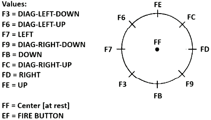
0A | [no known assembler command] Byte count = 1 Read a joystick status. With this it is be possible to test the right joystick for input. Stores value in the Accumulator Example: 00 6B LDV.B.05 ;sets display position with Register B 01 05 ;loading 05 for position to register B 02 0A ;grab joystick status and save to accumulator 03 B1 UNP.1 ;Unpack to Register 1 and 2 04 C1 OUT.1 05 C2 OUT.2 06 00 NOP ;No Operation, to cut on flicker 07 12 GTO.00 ;Goto step 00 08 00 This example toggles/outputs different characters associated with the different joystick positions.
0B | OTA Byte Count = 1 Output Accumulator Displays the value stored in Accumulator to the screen at the position defined in Register B
0C | [no known assembler command] Byte count =1 repeat ALL instruction Example: 00 61 LDV.1.3A 01 3A 02 C1 OUT.1 03 OC In this example, a man character is loaded in Register 1 and output to screen. The OC command will draw a row of men as the output is repeated. By inserting LDV.B.00 at the beginning of code, execution will repeat the display of the same character at the same spot. This appears to cause a quarter of a second pause and will loop slower than the Assembler command GTO.00
10 | BDB Byte count = 2 Branch on Decimal Borrow 10 [NN] or BDB.NN NN being the instruction/code step
11 | BDC Byte count = 2 Branch on Decimal Carry 11[NN] or BDC.NN NN being the instruction/code step
12 | GTO Byte count = 2 Goto a step (branch unconditionaly) Example: 25 GTO.03 Example tell code to goto step 03 in the assembler.
13 | BRZ Byte count =2 Branch when accumulator equals 0 (zero)
14 | GTS Byte count = 2 Goto a subroutine at instruction step 14 [NN] or GTS.NN NN being the instruction/code step
2[R] | BNE Byte count = 2 Branch if not equal 2[R] [NN] or BNE.[R].[NN] Where R is Register and NN is the Step number Example: 26 BNE.4.24 Example will branch to step 24 if Accumulator does not equal register 4
3[R] | BEQ Byte count = 2 Branch if equal 3[R] [NN] or BEQ.[R].[NN] Where R is Register and NN is the Step number Example: 26 BEQ.4.24 Example will branch to step 24 if Accumalator equals register 4
4[R] | BGT Byte count = 2 Branch if Register is greater than Accumulator. Example: 05 BGT.1.22
5[R] | BLS Byte count = 2 Branch if Register is less than Accum. Example: 05 BLS.1.22
6[R] | LDV Loads a value to a register. Example: 00 LDV.2.13 Example loads value 13 to register 2 Register B is special for it is used for setting position on screen. Example: 00 LDV.B.00 Example sets position on screen to 00.
7[R] | INP Input to Register
8[R] | PAK To combine two digits from two specified registers in the Accumulator. This instruction is used when working with numbers. Since the microprocessor reads the numbers in Binary, we must instruct it to combine two digits in order to produce and display a base 10number.The first register must always contain a number less than ten.
9[R] | LDA Byte count =1 Load a value to accumulator from Register. 9[R] or LDA.[R] Where R is the register.
A[R] | STO Bytes used = 1 Store Accumulator
B[R] | UNP Bytes used = 1 Unpack
C[R] | OUT Byte count = 1 Output displays output from a register Assember Example 05 OUT.1 Machine Hex Example 05 C1 Example outputs contents of Register 1 to screen
D[R] | SUB Byte count = 1 Subtract from Register
E[R] | ADD Add a value of a register to the Accumulator Assembler Example: 12 ADD.1 Machine Hex Example: 12 E1 Example will add the value stored in Register 1 into the Accumulator
FF | HLT Halt execution of code