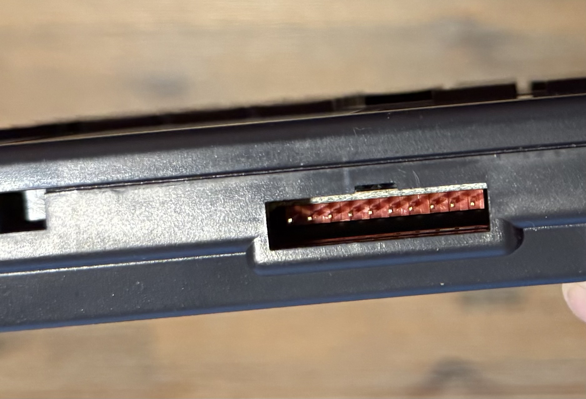
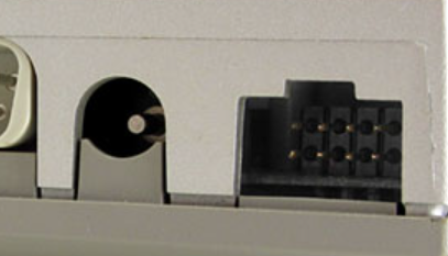
 Image: Dock-Bus on back of TI-95
TI-74 and TI-95 Dock-Bus 10-Pin Pinout
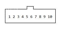 Pin # Signal Name Description
1 PO Power out -System Power Distribution Out (~6V).
2 PI 6.3V DC input for external power.
3 D0 Cassette data signal input (Pulse Width Modulation data from a cassette player).
4 D1 Part of (4-bit bi-directional data bus).
5 D2 Remote control line (output from the calculator to control a cassette motor, goes low to turn the motor off).
6 D3 Cassette data signal output (PWM data to be recorded to a cassette recorder).
7 HSK Handshake
8 BAV Bus Available handshake signal (bi-directional open collector).
LOGIC 0 (LOW) BUS IN USE OUTPUT
LOGIC 1 (HI) BUS AVAILABLE FOR INPUT
9 RESET
10 GND Common ground signal.
========================================================================
D0, D1, D2, D3 are bi-directional 4 bit data bus.
PI can be used power the TI-74 or TI-95 device.
========================================================================
Using cassete with Dock-Bus
The "Cassette Data Input" is pin #3 --> D0 with pin 10 for ground.
The "Cassette Data Output" is pin #6 --> D3 with pin 10 for ground.
voltage divider (e.g. 2 resisitors) (1k/10k/20k?) to match the voltage requirements your recorder.
A 100nF capacitor between voltage divider and mic-input could help
==========================================================================
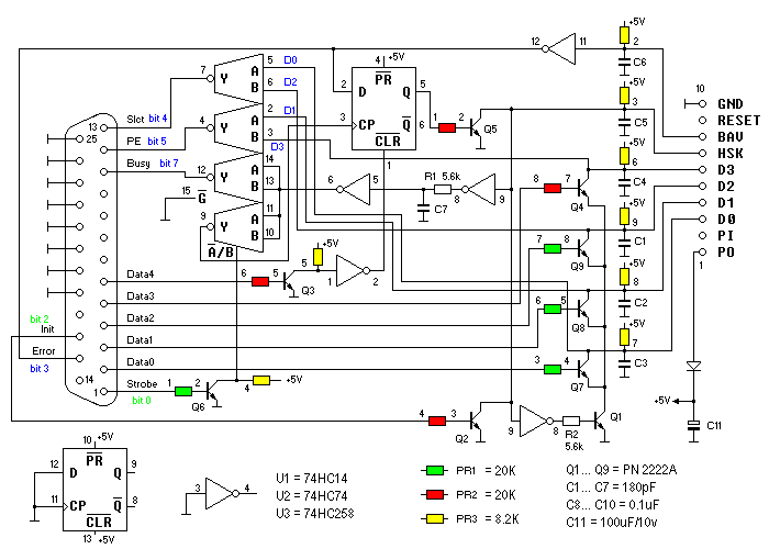
Dock-Bus interface to PC parallel cable interface
Pin # Signal Name Description
1 PO Power out -System Power Distribution Out (~6V).
2 PI 6.3V DC input for external power.
3 D0 Cassette data signal input (Pulse Width Modulation data from a cassette player).
4 D1 Part of (4-bit bi-directional data bus).
5 D2 Remote control line (output from the calculator to control a cassette motor, goes low to turn the motor off).
6 D3 Cassette data signal output (PWM data to be recorded to a cassette recorder).
7 HSK Handshake
8 BAV Bus Available handshake signal (bi-directional open collector).
LOGIC 0 (LOW) BUS IN USE OUTPUT
LOGIC 1 (HI) BUS AVAILABLE FOR INPUT
9 RESET
10 GND Common ground signal.
========================================================================
D0, D1, D2, D3 are bi-directional 4 bit data bus.
PI can be used power the TI-74 or TI-95 device.
========================================================================
Using cassete with Dock-Bus
The "Cassette Data Input" is pin #3 --> D0 with pin 10 for ground.
The "Cassette Data Output" is pin #6 --> D3 with pin 10 for ground.
voltage divider (e.g. 2 resisitors) (1k/10k/20k?) to match the voltage requirements your recorder.
A 100nF capacitor between voltage divider and mic-input could help
==========================================================================
Dock-Bus interface to PC parallel cable interface
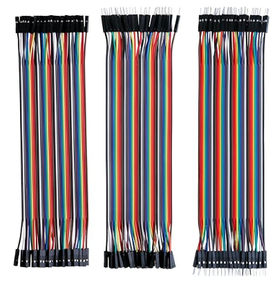
 Breadboard Jumper Ribbon Cables are cheap on Amazon and can be used to make various interfaces to devices.
 ==========================================================================
TI CC-40 HEX BUS PINOUT:
______
____| |____
| |
| 1 2 3 4 |
| |
| 5 6 7 8 |
| |
==========================================================================
TI CC-40 HEX BUS PINOUT:
______
____| |____
| |
| 1 2 3 4 |
| |
| 5 6 7 8 |
| |
 Pin # Signal Name FUNCTION
1 GND Ground - SIGNAL Return
2 BAV Bus Available handshake signal (bi-directional open collector).
LOGIC 0 (LOW) BUS IN USE OUTPUT
LOGIC 1 (HI) BUS AVAILABLE FOR INPUT
3 D1 Data Line BIT 1 (4-bit bi-directional data bus).
4 D0 Data Line BIT 0 (4-bit bi-directional data bus).
5 D2 Data Line BIT 3 (4-bit bi-directional data bus).
6 D3 Data Line BIT 2 (4-bit bi-directional data bus).
7 NOT USED NO CONNECTION
8 HSK HANDSHAKE LOGIC 0 (LOW) VALID DATA IS PRESENT ON D0-D3
===========================================================================
Using cassete with HEX-Bus
The "Cassette Data Output" is pin #6 --> D3 with pin 1 for signal ground.
The "Cassette Data Input" is pin #3 --> D0 with pin 1 for signal ground.
voltage divider (e.g. 2 resisitors) (20k?) to match the voltage requirements your recorder.
A 100nF capacitor between voltage divider and mic-input could help
Pin # Signal Name FUNCTION
1 GND Ground - SIGNAL Return
2 BAV Bus Available handshake signal (bi-directional open collector).
LOGIC 0 (LOW) BUS IN USE OUTPUT
LOGIC 1 (HI) BUS AVAILABLE FOR INPUT
3 D1 Data Line BIT 1 (4-bit bi-directional data bus).
4 D0 Data Line BIT 0 (4-bit bi-directional data bus).
5 D2 Data Line BIT 3 (4-bit bi-directional data bus).
6 D3 Data Line BIT 2 (4-bit bi-directional data bus).
7 NOT USED NO CONNECTION
8 HSK HANDSHAKE LOGIC 0 (LOW) VALID DATA IS PRESENT ON D0-D3
===========================================================================
Using cassete with HEX-Bus
The "Cassette Data Output" is pin #6 --> D3 with pin 1 for signal ground.
The "Cassette Data Input" is pin #3 --> D0 with pin 1 for signal ground.
voltage divider (e.g. 2 resisitors) (20k?) to match the voltage requirements your recorder.
A 100nF capacitor between voltage divider and mic-input could help