Back to TI-99 page
 Using other game controllers on the TI-99
|
The TI-99 computers uses one joystick port for two joysticks. I'm not aware of
any other system in the 70s or 80s that used this formula. But other joysticks
and game pads can work on the TI-99
Yes, there are many game controller adapters that you can purchase for the T-99.
But it is easy to make an single joystick or game pad adapter for well under $20.
$15 total for mine.
There are several solutions that don't require an iron or a circuit board.
In fact, most analog DB-9 port controller adapters are easy to make for a very
large selection of control pads and joysticks. This document will focus on the
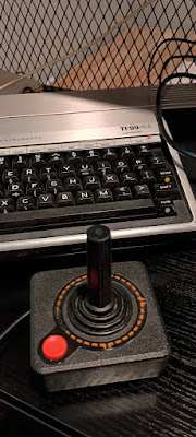
Atari CX-30 joystick, the Sega Genesis game pad, and the ColecoVision Flashback
Controller.
Why make an adapter? The TI-99 Joysticks are awful to use and they are also
now very hard to find. At no time have they been popular to use. Because of
this, even in 1982 people were using joystick adapters for their favorite joystick.
What supplies do you need?
- Wire. You can use Cat 3, Cat 5, Cat 5e, or Cat 6 cable as this will work for this task, although not required.
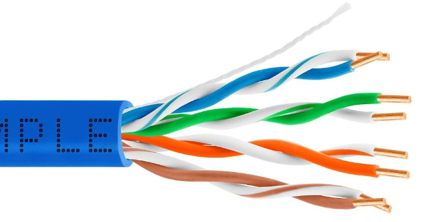
Using different colored wires helps with sorting the two ends correctly.
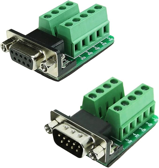
- DB-9 connectors. One male and one female. I use screw plate connectors to make easier.
Just need to strip the ends of each wire. There are many other options for your DB connectors.
- Optional heat-shrink tubing (for strength)
|
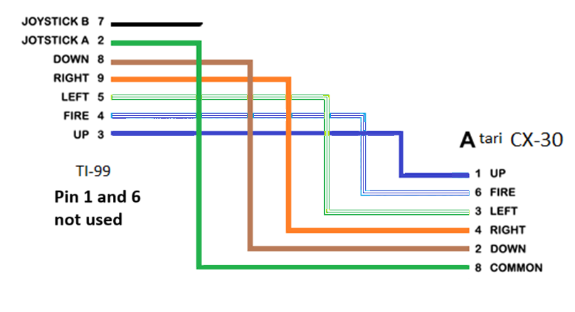
First, lets look at the pinouts of all four of these controllers.
TI-99 joystick(s)
___________
( 1 2 3 4 5 )
\ 6 7 8 9 /
# Use \_______/
- -------
1 not used ----
2 joystick 2 ground / common ----
3 Up Blue
4 Fire button Blue/White
5 Left Green/White
6 not used ----
7 joystick 1 ground / common Green
8 Down Brown
9 Right Orange
Atari 2600 CX-30 joystick
___________
( 1 2 3 4 5 )
\ 6 7 8 9 /
# Use \_______/
- -------
1 Up Blue
2 Down Brown
3 Left Green/White
4 Right Orange
5 Paddle B ----
6 Fire button Blue/White
7 +5 volts ----
8 ground / common Green
9 Paddle A ----
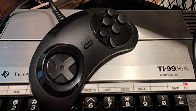 Sega Genesis game pad I have tested with 6 button controller.
___________
( 1 2 3 4 5 )
\ 6 7 8 9 /
# Use \_______/
- -------
1 Up Blue
2 Down Brown
3 Left Green/White
4 Right Orange
5 +5 volts -----
6 Button C (AKA fire button) Blue/White
7 ground / common
8 Select Button [also common] Green
9 Button B and A -----
So the Sega Genesis game pad and Atari CX-30 joystick can use the same pinout
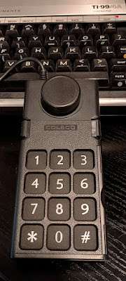 |
ColecoVision Flashback controller
     ___________
    ( 1 2 3 4 5 )
     \ 6 7 8 9 /
# Use \_______/
- -------
1 Down
2
3 ground / common
4 Up
5 Fire button 2
6
7 Fire button 1
8 Right
9 Left
|
Everything is connected and plugged in, Next - How to test the wiring:
Here is some super simple TI-Basic code I wrote for joystick direction read/test:
100 CALL JOYST(1,X,Y)
200 PRINT X,Y
300 GOTO 100
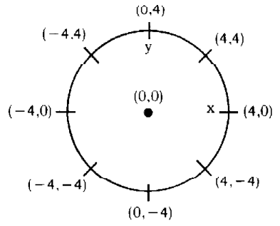
As you move (or don't move) the controller/joystick in each diretion, you should
see one of the following values for both X and Y - either 0, -4, or 4.
To test the fire button, use this code:
100 CALL KEY(1,K,S)
110 PRINT K,S
120 GOTO 100
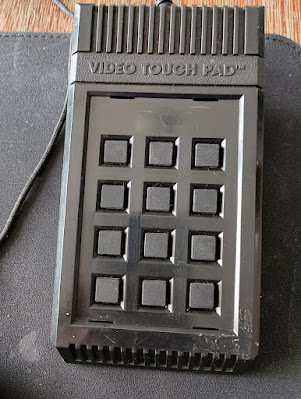
Using the Atari Video Touch Pad on the TI-99/4A
|
This part of the document is to to share the technical documentation of how to
use the Atari Video Touch Pad with the TI-99/4A. This device plugs into the
joystick port. So it makes sense that this device can have input
collected with the TI-basic command:
CALL JOYST
First, the number ordering of the 12 buttons
        [ 1] [ 2] [ 3]
        [ 4] [ 5] [ 6]
        [ 7] [ 8] [ 9]
        [10] [11] [12]
Here is the Mapping without any adapter used and plugged into joystick port:
    CALL JOYST(1,X,Y)
    [no mapping]

    CALL JOYST(2,X,Y)
    Button 4 sends the left  control input   X = -4
    Button 5 sends the right control input   X =  4

    with adapter:
    Button 6 is fire button.

   TI-99 joystick(s)
     ___________
    ( 1 2 3 4 5 )
     \ 6 7 8 9 /
# Use \_______/
- -------
1 not used                         ----
2 joystick 2 ground / common       Used  -- ---
3 Up                               ----    |  |
4 Fire button                      ----    |  |
5 Left                             Used  --   |
6 not used                         ----       |
7 joystick 1 ground / common       ----       |
8 Down                             ----       |
9 Right                            Used  -----
|
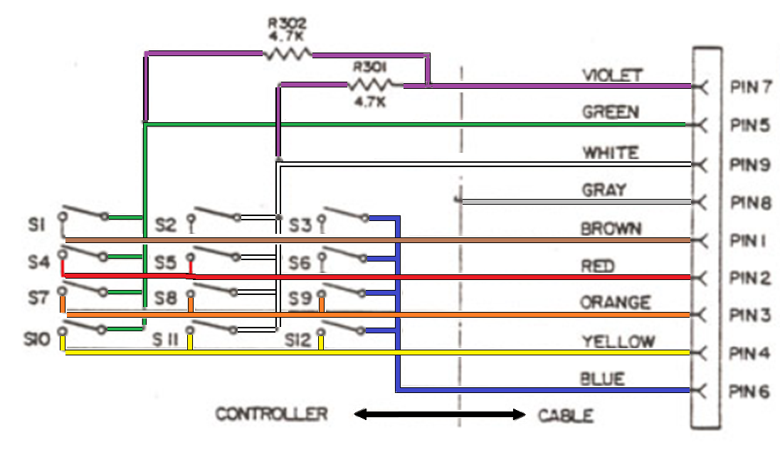
1, 2, 3, and 4 pins are primary on the controller. the TI does not use 1, and 2 is the common for joystick 2.
for the first two columns of buttons, traffic is alway routed out 5 or 9 (least resistance) because of resisters on pin 7.
Moving pin 6 to 4 will give us a fire button on button 5.
After three days of tinkering, my choice to use with the TI-99/4a is a Sega Genesis game pad.


 Using other game controllers on the TI-99
  Sega Genesis game pad I have tested with 6 button controller.
___________
( 1 2 3 4 5 )
\ 6 7 8 9 /
# Use \_______/
- -------
1 Up Blue
2 Down Brown
3 Left Green/White
4 Right Orange
5 +5 volts -----
6 Button C (AKA fire button) Blue/White
7 ground / common
8 Select Button [also common] Green
9 Button B and A -----
So the Sega Genesis game pad and Atari CX-30 joystick can use the same pinout


